CNC Plasma Tables
-
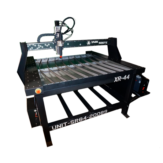
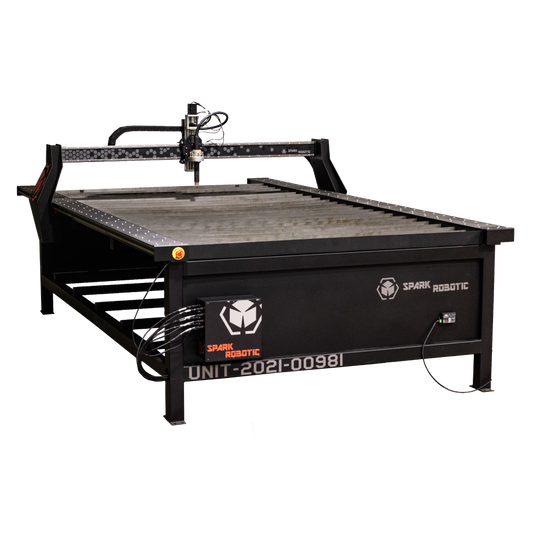
XR44 - 4x4 CNC Plasma Table
Regular price $9,499.00Regular priceUnit price per$11,499.00Sale price $9,499.00Sale -
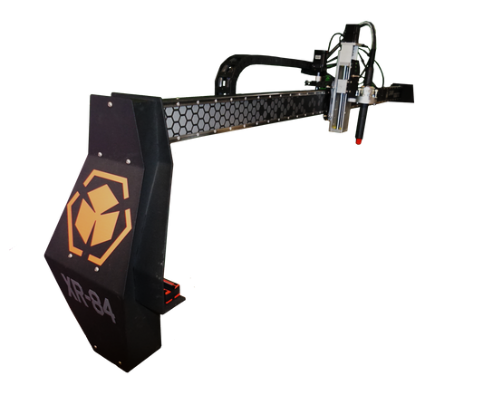
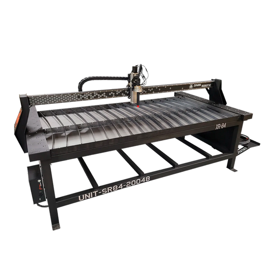
XR84 - 8x4 CNC Plasma Table
Regular price $10,499.00Regular priceUnit price per$12,499.00Sale price $10,499.00Sale -
XR51 - 5x10 CNC Plasma Table
Regular price $12,499.00Regular priceUnit price per$14,499.00Sale price $12,499.00Sale
Plasma Cutting System & Consumables
-
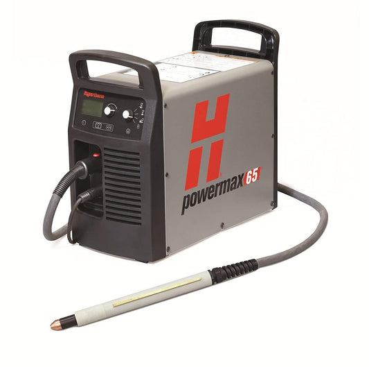
Hypertherm® Powermax Plasma Cutters
Regular price From $2,900.00Regular priceUnit price per -
SterlingCool-PlasmaCut
Regular price $177.00Regular priceUnit price per -
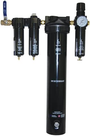
Air Dryer System
Regular price $870.00Regular priceUnit price per -
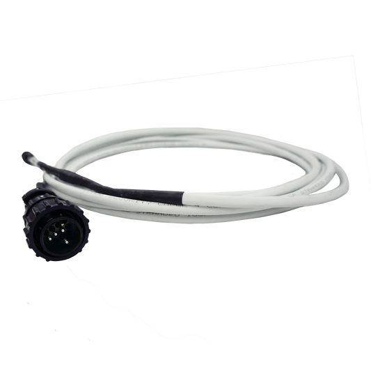
CPC Interface Cable
Regular price $185.00Regular priceUnit price per -
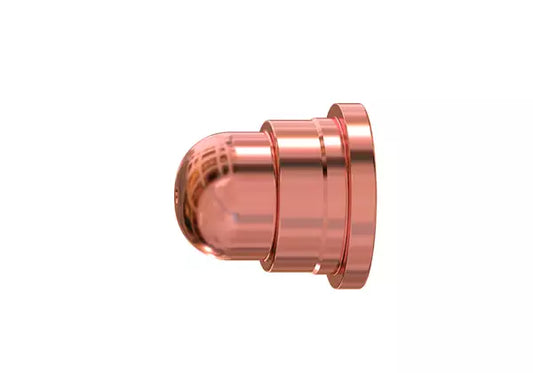
Hypertherm® 45 Amp FineCut™ Nozzle (Qty 5) #220930
Regular price $47.50Regular priceUnit price per -
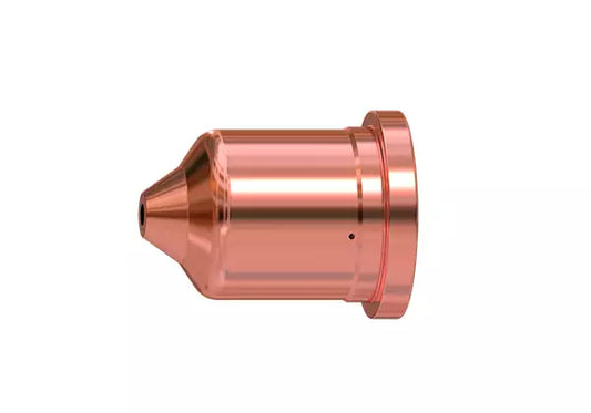
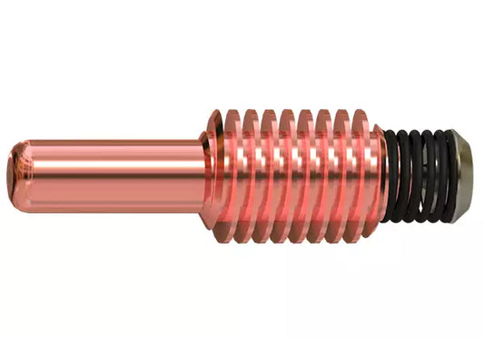
Hypertherm® 85 Amp Air/Nitrogen Nozzle (Qty 5) #220816
Regular price $47.50Regular priceUnit price per -
Hypertherm® Bulk Pack Shield Duramax Mechanized 15-85 A (Qty 10) #228763
Regular price $227.00Regular priceUnit price per -
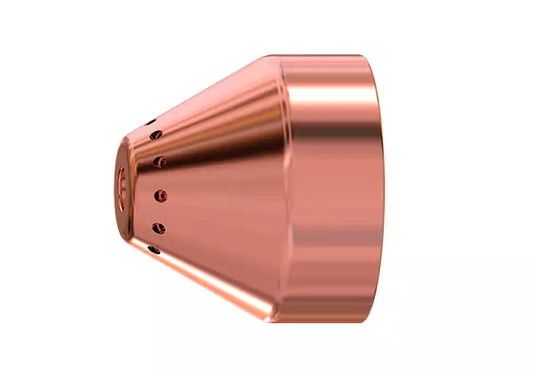
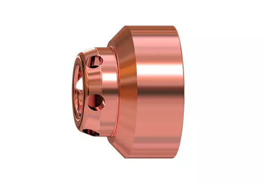
Hypertherm® Mechanized Shield #220817
Regular price $23.90Regular priceUnit price per -
Hypertherm® FineCut Ohmic Shield #220948
Regular price $19.20Regular priceUnit price per -
Hypertherm® Bulk Pack Nozzle Duramax 85 A (Qty 25) #228760
Regular price $225.00Regular priceUnit price per -
Hypertherm® Bulk Pack Nozzle Duramax FineCut 30-45 A (Qty 25) #228761
Regular price $225.00Regular priceUnit price per -
Hypertherm® Bulk Pack Electrode Duramax 10-105 A Contains (Qty 25) #228767
Regular price $296.00Regular priceUnit price per


CNC Router Tables
Router Accessories
D.I.Y. Builder Tables
-
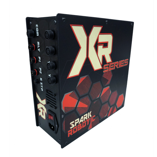
CNC Plasma Control / RetroFit
Regular price $3,000.00Regular priceUnit price per -
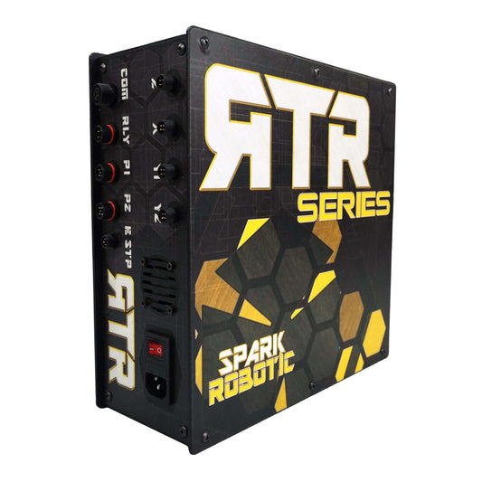
CNC Router Control / RetroFit
Regular price $3,000.00Regular priceUnit price per -
D.I.Y. - Plasma Gantry Kit
Regular price From $7,849.00Regular priceUnit price per